![]()
![]()
![]() Under Construction
Under Construction
The purpose of the DFA Dormitory is to provide a safe area where detectors can be temporarily stored under bias voltage in a controlled environment. Long term leakage current will be monitored so that high leakage detectors can be culled out. The dormitory system was placed in operation in late October 1997 with an initial run with 5 separate fully bonded DFA's. The initial test run covered a span of 7 days with detectors biased at 60 volts. Future DFA burn in voltages will use the operating voltage as established by Pisa typically in the area of 40 volts. . The bulk and the guard ring leakage currents are monitored continuously during the period.
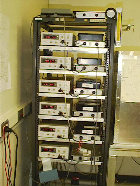
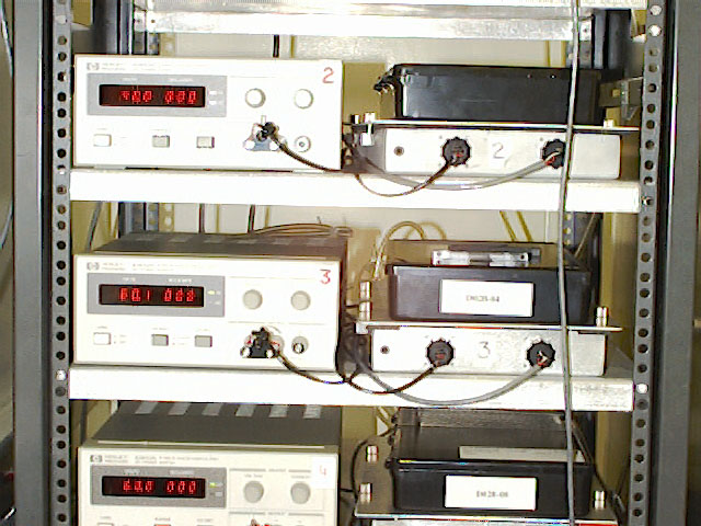
Here is a photo of the 6-dorm stack showing the separate power supplies connected to the individual dorm chambers. The box at the top left holds the temperature/ humidity sensor along with signal conditioning which has a sample of the dormitory dry air routed to it. The small box at the bottom of the rack is the dorm interface into which all of the sense lines from the dorm chambers connect. A 50-conductor ribbon cable (from which the box is hanging) connects back to the National Instruments Data Acquisition board, which is mounted in the PC. The gauges on the upper right of the stack are used to monitor the flow and pressure of the dry air into the dorms. The dorms are powered by separate HP E3612A power supplies with a range of from 0 - 60 vdc / 0 - 120 vdc with 0.1v resolution and a 2mA minimum current limit employing a digital voltage and current display with independent adjustment on voltage 0 < V < 60 vdc with 0.1 vdc resolution
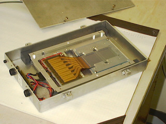
Silicon Detector positioned in Dorm (note bias connector on left)
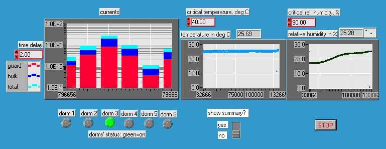
Main Screen for Dorm Monitoring System
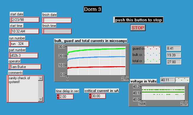
The Individual Screens display the time history of the bias currents and the applied voltage. View the real time data collection process on a sample part by clicking here. The DFA part number and the test start time is also displayed. The sample rate of the data collection can be adjusted from this front panel. Data from this vi is collected every hour into an Excel spread sheet file for post analysis. The data records show the time history of all of the monitored parameters.
Signal conditioning (DFA Dorm Electronics Schematic) for the leakage current measurement consists of a voltage measurement across a 10k-ohm series resistor to provide the required current resolution. Detector current is limited by a 1N5283 200 uA constant current diode (replaces R5 in the attached schematic). The 1N5245 15 volt zener diodes provide over voltage protection for the analog to digital converter. The 8 channel multiplexer U1 provides for low data rate acquisition of DFA operating voltage data. Data collection is accomplished using the National Instruments PC-LPM-16PnP General purpose I/O Board which provides 12 bits of resolution digitized over a 5 volt range with 16 separate analog input channels. . This provides for 36 mV of resolution for the operating voltage and 120 nA of leakage current resolution.
(Last update on 3/4/1998 by SB)
Questions? sburke@hep.ucsb.edu