Portable Visible Light Sensors (PVLS) for Physics Labortories.

Created by Wing H To, UCSB Physics: 22 April 2013
Last Updated On: 26 April 2013


Data Summary of PVLS:
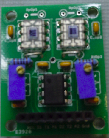
  • A simple visible light detector in the wavelength range betwen 400 to 800 nm.
  • Ability to read out both analog and digital output from the photodiodes.
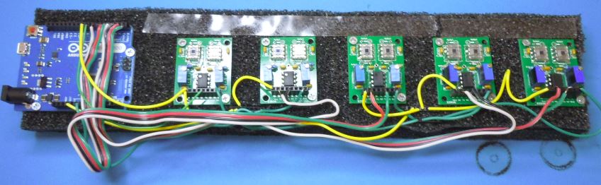
  • Operate with a single Arduino for power supply (Single 3.3V) and readout by the Arduino.
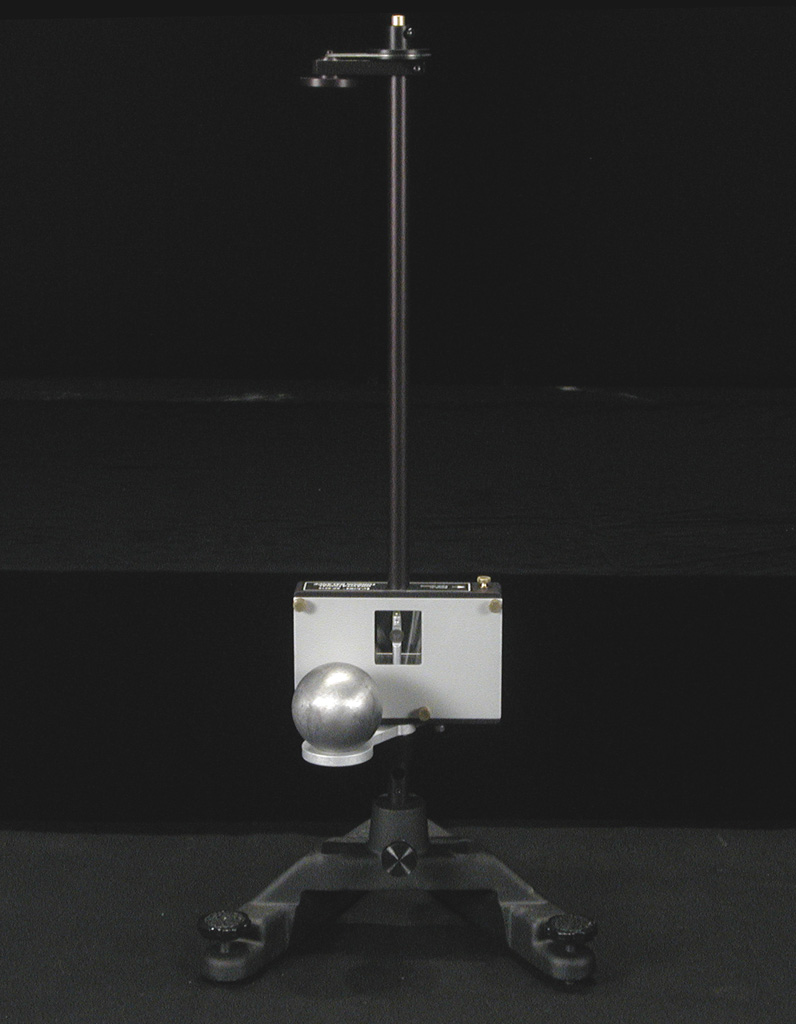
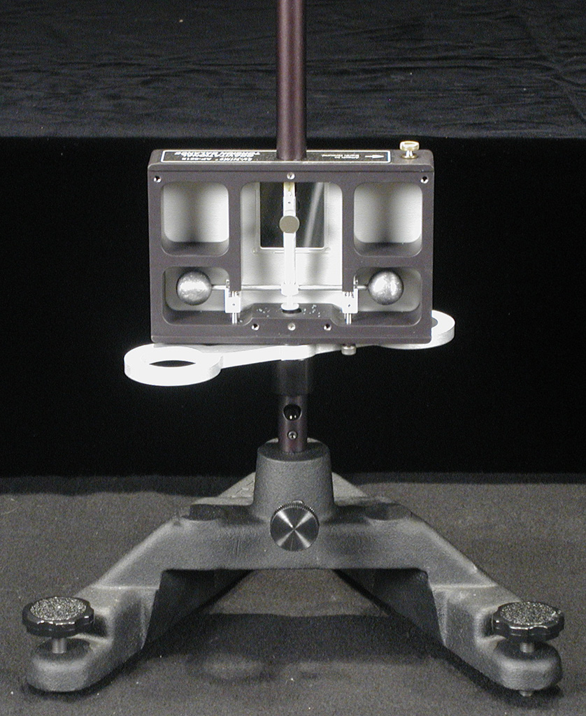
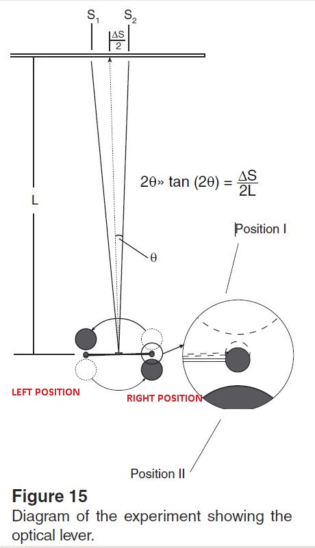
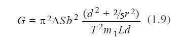
  • Set of 10 sensors were tested on the Cavendish experiment.
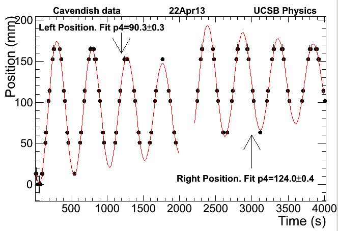
  • Sample data taken for the Cavendish experiment using the PVLS
  • Click on image to see full size plot.


PCB Design:
this is image #1 this is image #2
Board Specifications:
2 Layer, 1 oz copper PCB.
1.25" x 1.60"
8 mil spacing, 20 mil min drill size.
Designed in EAGLE PCB Software from CAD Soft USA
this is image #1 this is image #2

this is image #1 this is image #2
IC:
OPT101 - Photodiode with an built-in amplifier.
LM393 - Single supply discriminator.

Passives:
RpOp1,2: Open
C_Op1,2, CsOp1,2, UnMarked Cap slots: 0.1 uF
RsOp1,2: Short or 0 Ohm.
RtOp1,2: 1k Ohm.
Pot Slots: 10k Potentiometers.

Connectors:
Vcc: 3.3-5 V.
D1, D2: Digital output [0,Vcc].
T1, T2: Discriminator threshold Vcc/2 normally.
A1, A2: Analog output from photodiode

Mods:
Needed to add resistor to LM393 digital output to pull it's output up to Vcc (not in PCB design).
10k Ohm between LM393 Pin1&8, 10k Ohm between Vcc and d2.


The Photodiode (OPT101):
  • OPT101 datasheet
  • Single Supply 2.7 to 36V.
  • Large active area 0.23x0.23 cm^2.
  • High spectral response between 400-1100 nm.
  • 8-Pin DIP Package.

The Discriminator (LM393P):
  • LM393 datasheet
  • Single Supply 2.0 to 36V
  • Low Input Offset 5.0 mV (max @ 30V).
  • Dual channel.
  • 8-Pin DIP Package.

Read out using Arduino:
  • Arduino Leonardo Spec

Arduino is used to supply 3.3V and read out digital channels on each sensor.
See image for an example setup.
Cavendish Sensors
Arduino Read Out Codes:
Arduino codes to readout each channel digitally. The output is piped to the serial port connected to the Arduino.
Sample codes for read out is shown below.
  • 4 Channel Readout

Data taken from Cavendish experiment:
  • Gravitational Torsion Balance Manual
this is image #1 this is image #2
Diagram of the mass position on the cavendish appraratus.
Mass Positions

  • PVLS sensors are placed at L = 1551±5 mm.
  • Each sensor pairs are 50.8±2.54 mm, and the sensors on each board are 12.7±0.2 mm.
  • The large masses (1.5 kg each) are place on the left position and data collected for 2000 seconds.
  • The reflected laser position and time are recorded via an Arduino connected to a windows laptop in Broida 3314.
  • Arduino codes for Cavendish
  • This is repeated for another 2000 seconds with the masses on the right position.
  • The data are readout through the serial port on the arduino with an uncertainty in time of 50 ms.
  • Data in left position
  • Data in right position
  • Root script to analysis the cavendish data.
Data points and Fit Results
Fit function define in root: TF1 * DampSineFit = new TF1("DampSineFit","[0]*sin([1]*x-[2])*exp([3]*x)+[4]",0,RANGEMAX);
[4] Fit Parameter on left = 90.3±0.3 mm
[4] Fit Parameter on right = 124.0±0.4 mm
Formula for G

Table 1 Cavendish apparatus data

r, radius of the small mass. 9.55 ±0.1 mm. Estimation of a smooth sphere 1%.
d, distance between the center of the small masses. 50.0 ± 0.5 mm. Estimation also 1%.
b, distance between the centers of small and large masses. 46.5 ± 2 mm. Estimated to be less than 2 mm by sight.
m1, large sphere mass. 1.50 ± 0.15 kg. 1%
L, distance from the mirror to the center of the sensor plane. 1551 ± 7 mm. From 1450±5 mm along the horizontal and 550±5 mm along the verticle
Period T 486.5 ± 0.6 s. ± 0.58 s from fit and ± 0.05 s from readout delay.
ΔS, change in the oscillation's mean value. 33.8 ± 2.5 mm. ± 2.5 mm from distance between boards. 0.2 mm from distance between sensors. 0.1 mm from fit.
G_measure = (6.64 ± 0.61) x 10-11 m3kg-1s-2