Connecting the Oscilloscope
It may be helpful to have a picture available for reference before connecting the cables.
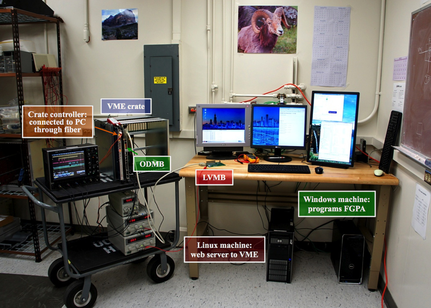
The ODMB should be connected to the LVMB by a 50-pin cable, and the LVMB grounded (by connecting to the ground of the bottom-most power supply). It is advisable to connect the ground last to avoid putting any stress on the connection to the LVMB, which is potentially weak. Roughly at the center of the ODMB are 16 test points in two rows of eight. The left-most four test points in the bottom row should be connected to the four channels of the oscilloscope.
After the cables are attached, the three power supplies can be turned on, starting with the top power supply and end with the bottom. The top power supply should be at about 5V and 2.5-3 amps. The middle should be at 3.3-3.4V and roughly 6 amps. The bottom voltage can be adjusted from 0-10V and should have less than 0.1 amps of current. The oscilloscope should also be turned on.
Voltage Measurement/Reading Signals
Before proceeding, the odmbdev page needs to be active. If it is not, you will need to run the appropriate script (see the TriDAS documentation for instructions). Once it is running, go to the odmbdev page.
We will also need to set up the oscilloscope properly. The four channels (we won't actually use channel four for now, so this can be shut off if desired) should separated vertically and set to 2V per division. The horizontal time scale should be set to 5 microseconds per division. A timebase (horizontal delay) of about -15.3 microseconds will capture most of the signal on the screen. The trigger should be set to whichever channel is connected to the left-most test point on the ODMB (as this will be the clock channel). It should be in edge mode (either positive or negative slope is fine) with a DC coupling and a level of about 1V. The trigger should be set to either "normal" or "single" mode.
In the text box (or via an input file), type the command "W 8020 0" to select the first ADC chip on the LVMB (the zero is the number of the chip being selected, counting up from 0), and then "R 8024" to confirm that the correct chip is selected. Once this has been done, the command "W 8000 89" will write the control byte 89 to the ADC. The 89 is a hexadecimal representation of the control byte 10001001. The first bit is always 1 and indicates the start of the control byte. The next three are a binary representation of the number of the channel begin read from (zero through seven. The fifth and sixth indicate that we are measuring the voltage on a scale of 0-10V (see the CMS EMU DMB/CFEB Programmers Manual). The last two bits indicate that we want to run in normal operation mode with an external clock (again, see the Programmers Manual).
When the command "W 8000 89" is entered, the oscilloscope should trigger. Channel one should show the signal from the clock, channel two should show the 89 in binary form, and channel three will contain a 12-digit binary representation of the voltage. To extract the voltage measurement, one reads the value of channel three at the positive-slope edge of the clock signal. The 12-digit binary number is a numerator which should be divided by "111111111111" to give a fraction. This fraction is then multiplied by 10V to obtain a voltage reading. Running the command "R 8004" will display the numerator in hexadecimal form for confirmation.
Disconnecting
Turn off the power supplies from the bottom up, and then disconnect the cables. Also, make sure to remove the LVMB ground first so as not to damage the connection.