![]()
![]()
The HDI Adaptor Cable Assembly was developed to provide a means for connecting to the HDI without using the SVT kapton tails. This method of connection will be used during module and HDI production testing in the lab at Pisa, Milan, and UCSB. It will also be used at LBNL to test the modules in the shipping fixtures before they are mounted on the cones.
HDI ADAPTOR CABLE ASSEMBLY
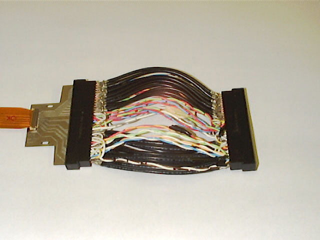
The separate connections routing from the HDI to the Matching Card are, the 4.6 cm flex Z and Phi side jumpers (item 1) connecting to the Berg connectors on the Card Edge Connector double sided pc board (item 2) which connects to the Adaptor Cable Assembly (item 3) which connects to a second identical pc board, as item 2, which makes connection to a pair of 5.0 cm flex jumper pairs (item 4) terminated to the Berg connectors on the Matching Card. Details related to each of the items is outlined below.
ITEM 1: 4.6 cm Flex Jumper (see JUMPER.PS for more details)
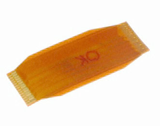
Dimensions: 46.0 x 16.5 x 0.142 mm (21.0 mm wide at mid section)
Material: 0.101 mm Kapton (Polyimide) 38 um soft copper with phosphorus 0.76 um gold plate at ends Insulation: 3 um varnish Berg connector spec is 150 + - 50 um for tail thickness.
Notes: The length of this jumper has been optimized for the UCSB Ring Frames. Due to the tight packaging of the layer 1 and 2 modules, longer (12 cm) flex circuits will be used for tests in the UCSB shipping boxes. We are assuming that for the layers 4 and 5 the standard 4.6 cm long jumpers will be adequate for both production testing and testing in the shipping box. The flex tails used to connect to the matching card will be 5 cm long.
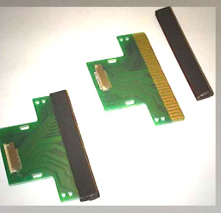
ITEM 2: Card Edge Connector Double Sided PC Board (see BERGZFBM.EPS or BERGLYR3A.PS for more details.
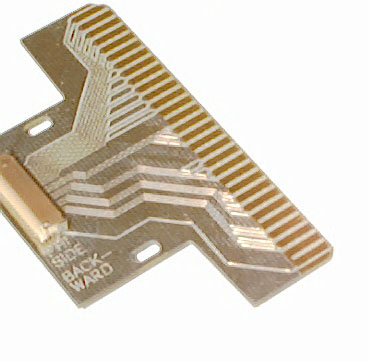
Dimensions: 78.74 x 46.99 mm Z Backward / 78.74 x 44.17 mm Z Forward (see bzfbbot.eps and bzfbtop.eps for details)
Material: 0.062 (1.57 mm) double sided G10 glass epoxy board
Card Edge: 30 ea gold plated traces on 0.100 centers both sides , mates with AMP Connector PN 1-583717-3 dual 30 contact, http://connect.amp.com/AMP/bin/AMP.Connect?C=1&M=BYPN&PN=1-583717-3 (user: sburke, password: samuel).
Connector: 30 pin Berg surface mount connectors on both sides Berg PN 87768-130 (see http://www.bergelect.com/catalog/ch01/p1-1.html)
Notes: Because the card edge connectors have to be mounted in the existing UCSB Ring Frames, two slightly different versions have been designed, one for the forward Ring Frames and one for the backward Ring Frames. It is expected that the Pisa and Milano groups will only be using either the forward or the backward model. We need to know which model the two groups would like to use.
ITEM 3: Adaptor Cable Assembly (see electrical schematic jumper1.eps for details)
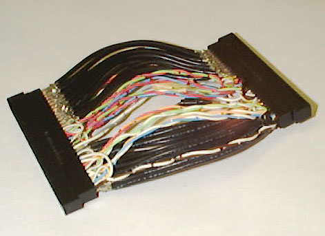
Dimensions: 5.8 cm length for UCSB Adaptor (measured from outside edge of connectors) 4 cm cable bundle width Connector: AMP PN 1-583717-1 Dual 30 contact with crimp pin AMP PN 583616-5 for 28 - 24 AWG.
Notes: The length of this cable assembly has been chosen with the UCSB setup in mind. It can be made shorter or longer for the Pisa and Milan test setups.
Electro Static Discharge PC Card Edge Protectors: After the HDI Tailsaver connections have been made to the HDI, the Atom chips become susceptible to damage from electrostatic discharge. The 3M 5220 PCB Edge Protectors reduce this hazard by electrically connecting the tabs of the board, keeping all leads at the same electrical potential. The loaded ring frames can then be handled more safely. While not every device on the board will be protected, it will reduce the possibility of damage to the components that are directly connected to the PC connector tabs. The flexible plastic construction of the 5220 edge protector prevents scratching of plated PCB contacts. The cross sectional dimensions of the protectors are 0.21" x 0.40" with the length cut to 3.2" to match the width of the Adaptor Connector. The resistance measured using a VOM with probe tips 1.0 cm apart on the protector is near 10 kohms.
ITEM 4: 3M PCB Edge Protector
(updated 10/16/98 SB)
Any comments or questions? Please send e-mail to Sam Burke